
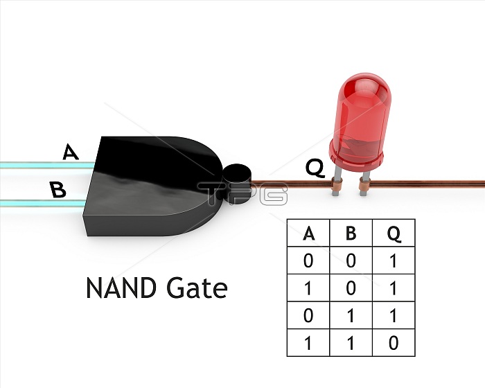
NAND logic gate, diagram. Logic gates are electrical circuits that are wired so as to produce a specific output according to logical rules. The diagram shows two inputs (A and B) and an output (Q). A NAND gate (AND plus NOT) reverses the operation of an AND gate and only outputs off if both its inputs are on, as shown in the table at lower right. The inputs here are both on, with the LED (light-emitting diode) at right in the off (unlit) state. The shape of the logic gate shown here is that of the NAND symbol used on circuit diagrams. For a series of diagrams of the seven basic logic gates (NOT, OR, AND, NOR, NAND, XOR and XNOR), see images C045/9800 to C045/9806.
| px | px | dpi | = | cm | x | cm | = | MB |
Details
Creative#:
TOP24609549
Source:
達志影像
Authorization Type:
RM
Release Information:
須由TPG 完整授權
Model Release:
N/A
Property Release:
N/A
Right to Privacy:
No
Same folder images:
 Loading